
There’s a wide variety of possible scenarios that may require a service technician, facilities manager, or manufacturer’s rep to troubleshoot a commercial pump. Regardless of the circumstances, using a methodical approach is best when diagnosing a pumping problem.

At Taco Comfort Solutions, we’ve found that 80% to 90% of the calls we receive about commercial “pump issues” are in fact system issues. That’s not so say that the pump is never the cause of the problem; it’s just easy to point to the pump before verifying that the system meets the design for which the pump was selected.
Distinguishing between a pump problem and a system problem often requires a good bit of information gathering.
Methodical Approach
We use a multi-step process when identifying issues involving commercial pumps. This article will cover the process so that you’re prepared to determine what’s causing an issue you may face in the future, whether you handle it on your own or consult the pump manufacturer’s support team.
Usually, troubleshooting support calls come from the rep or customer. When it’s the customer that calls, I bring the rep into the conversation before proceeding through the following steps:
1. Stay Calm
The person looking for help may be the engineer or the installer. Regardless, the caller is sometimes panicked. We explain that we need to be methodical and collect as much information as possible.
Panicking or jumping to conclusions is not helpful. In fact, jumping to a conclusion is counter-productive because it may cause us to overlook the real issue.
2. Identify the Problem
Here, I ask the caller to briefly explain what’s going on. For example, they have a chilled water system and the water flow is low. They may tell me that they’re sure it’s the pump, but we don’t know that yet. We can be fairly certain that there’s a flow problem, but we’re unsure of its cause.
3. Interview Process
At this point we need more information. I ask specific questions. For example:
- Is this a water-cooled system?
- If so, is the issue on the chilled water or condenser water side?
- How many pumps are in the system?
- Which model pump?
If it’s not a Taco pump, we’ll still help resolve the issue for the customer, but they need to understand that I won’t have the pump data on hand. There’s a chance that we can still identify if there’s something wrong within the system, but without the pump data, we may not be able to reach a conclusion.
Once we have the pump model, we need to know the design operating conditions. These are the conditions for which the pump was specified. We also need to know the actual, real-time pump performance. We’ll compare design conditions and actual performance information later.
This means that someone onsite will be required to measure the flow and pressure drop across the pump. If there are pumps in parallel, it’s best to measure flow across one pump at a time. This establishes the performance of the pumps individually.
If the people onsite are reading less flow than design, we need to know what they’re using to measure flow. The preferred method is a calibrated flow meter, either a permanently installed unit or a strap-on, ultrasonic meter. Measuring the Delta-P across the pump is an indicator, but it’s not conclusive.
4. Data Collection
The importance of photographs can’t be overstated. There’s no such thing as too many images. Photos can help determine if the system was piped according to the original design and identify easily overlooked issues like placement of meters. Collect as many images as possible and develop a file. The earlier you have these images in the troubleshooting process, the better.
I like to review these images while I’m on the phone with the person that took them. This allows me to navigate the images and ask further questions that may arise.
We also need access to the piping diagrams. If diagrams aren’t available, I ask for a hand sketch.
Once we have images and a diagram or sketch, we need to collect electrical data. Volt and amp readings should be taken at the motor input by a licensed electrician. If the pump is equipped with a variable frequency drive (VFD), the readings should be taken at the input of the drive, not the motor. This is because the VFD modifies the voltage going to the motor.
There are other considerations when a VFD is present on the pump. Ideally, the electrical data at the drive should be taken at full speed. This means that the flow and pressure differential must also be measured at full speed.
Make note of the pump RPM. This allows us to verify that the pump is in fact operating at the correct speed and in the correct direction.
The next thing we need is manufacturer data. It’s quite common for people to think they have pump model X, only to realize it’s a different pump when they send a picture of the pump tag. This is another reason for photos. We need to confirm the pump model.
After the pump model is known, the single most important piece of manufacturer data is the pump curve. The installation and operation manual is also critical. The next thing we need is the field data. Taco calls this the commercial pump troubleshooting report. This sheet is available as a download from the Taco website.
This is the minimum amount of data we like to collect.
5. Analyze the Data
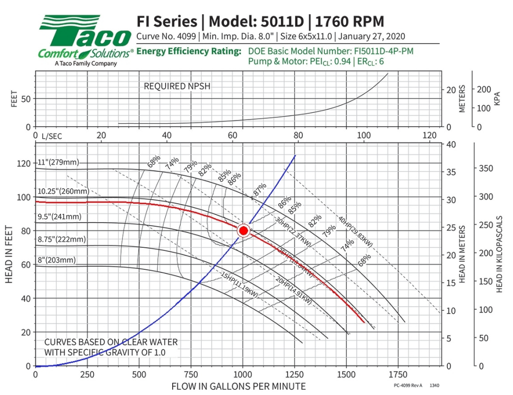
Let’s assume this is a Taco FI Series 5011D. Referencing the pump curve, we find that in a single-pump configuration, this unit provides 1,000 GPM at 80 feet of head. The red line represents the pump curve and the blue line represents the system curve. In this example, the customer didn’t actually measure the flow. Instead, they measured the pressure differential across the pump and reported that it was 92 feet of head.
Keep in mind that there’s a correction needed here. The 5011D is an end-suction pump, which typically has a larger inlet than outlet. So we need to correct for velocity.
They did this and 92 feet was correct, meaning that they intersected the pump curve line at 750 GPM.
We would prefer to have the flow measured independently so that we could check it, either through a permanently installed flow meter or a non-invasive, strap-on ultrasonic flow meter that’s been recently calibrated.
In this scenario, we find that the pump is operating on the pump curve but at a different pressure drop, which hints at a system issue instead of a pump issue. Looking at the pump curve, we know that this unit should be operating at 25 horsepower while providing 1,000 GPM at 80 feet of head. Given the field-collected flow and pressure, the pump curve shows that the pump should be operating at roughly 21 horsepower.
Determining the actual horsepower of the pump in the field requires a number of electrical calculations.
We use the field data recorded by our electrician (at 1,760 RPM) to calculate the actual pump horsepower. The efficiency and power factor of the pump is listed on the pump’s nameplate. These numbers are a critical component in the calculation.
When we calculated the horsepower in this example, we found that the pump was operating at 21 horsepower, as expected. This confirmed that the reason we’re not getting the proper flow is that there’s more system resistance than was originally anticipated.
We can also ask the people in the mechanical room for the shut-off head. Keep in mind that this number can be greater or less than the published value by as much as 8 feet. To determine the shut-off head, throttle back the discharge valve and isolate it for a few seconds. The operator should be able to measure the pressure differential across the pump. In this case, the shut-off pressure should be around 97 feet, which will confirm that the impellor diameter is as specified (10.15 Inches) and indicated on the pump curve.
6. Recommend a Solution
Everything we’ve done so far leads us to believe that there’s a pressure drop in the system beyond what was anticipated. So I took another look at the piping diagram and photos. In this scenario, there was only one difference between the piping diagram and what existed in the mechanical room.
The photos revealed a basket strainer installed between the cooling tower and the suction side of the pump. This, we came to learn, was added after the initial installation, and was not part of the design. Despite the fact that the published pressure data for the strainer was 2 feet, it was causing a 12-foot pressure drop.
At this point, it was up to the customer to determine what to do about the strainer. Maybe it can be removed, maybe it can be oversized, but suffice it to say that this was not a pump issue.
7. Additional Considerations
There are a few key elements to troubleshooting a pump issue that weren’t discussed in the above example.
The use of a glycol mixture instead of pure water will significantly raise pumping resistance within a hydronic system. The dilution of the glycol, along with the temperature of the system fluid, will have an impact. The more glycol used, and the lower the fluid’s temperature, the greater the resistance.
When measuring the pressure differential across the pump, the difference in elevation between the inlet gauge and the outlet gauge can have an impact on collected data. If the gauges are at different elevations, a correction needs to be made before the readings can be used in any calculations.
Having calibrated gauges and meters is the only way to ensure that the readings taken are accurate. Most suppliers of gauges and meters will check the calibration of the instruments before shipping them.
There are three types of pressure gauges readily available: conventional, compound, and digital. If conventional gauges are used, keep in mind that the unit will read zero any time the pressure is at or below zero. It’s very unlikely that pressure will ever be zero.
In one instance, I asked the contractor to exchange the existing conventional gauge with a compound gauge. After doing this, it became evident that there was negative pressure at the gauge and the negative pressure was causing the pump to cavitate. As a result, it’s better to install compound or digital gauges than conventional gauges in most cases.
As you troubleshoot a pump, keep in mind that, more often than not, the pump isn’t the issue. While the pump can be the problem, it’s far more likely that there’s an issue with another component in the system: perhaps a deviation from the engineer’s piping diagram, a faulty component, or an installation mistake.
The best approach to quickly resolve the issue is to eliminate variables by collecting and reviewing information. The more information and photos that can be referenced, the faster you are likely to come to a conclusion.
Richard Medairos, P.E., is senior systems engineer and director of commercial training for Taco Comfort Solutions.